
Assembly Instructions
Tools Needed
Hardware List
Provided
Hex wrenches – “H”
- 3/16 inch
- 5/32 inch
- 1/8 inch
User supplied
- Phillips head screw driver
- Adjustable wrench or standard wrench set
This hardware is included and needed for assembly – other hardware-parts are pre-assembled.
Lock nuts – 6
- 6 @ size 10
Bolts – 16
- 8 @ size 3/4 in. – “A”
- 2 @ size 1 in. – “B”
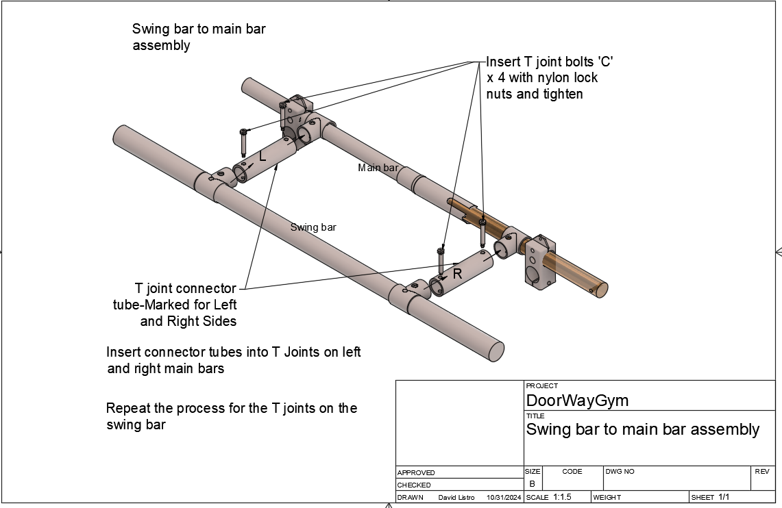
- 4 @ size 1 1/4 in. – “C”
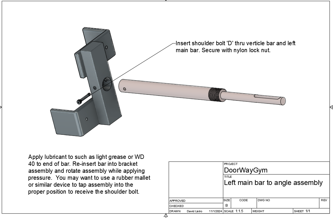
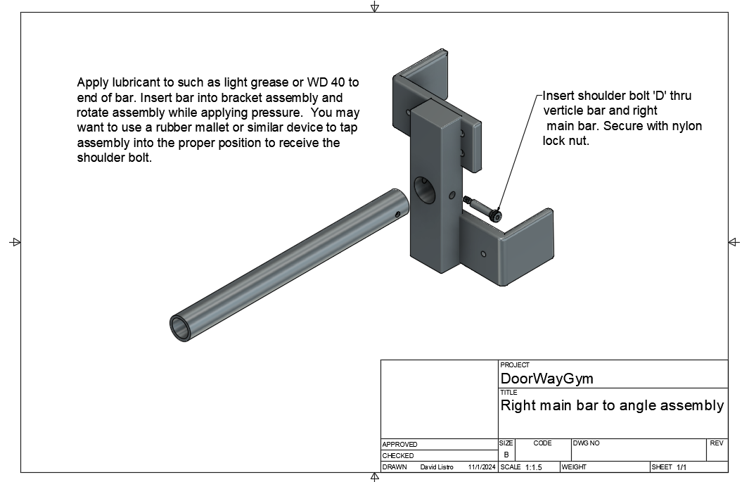
- 2 @ size 1 1/2 in. – “D”
Washers – 6
L angels – 4
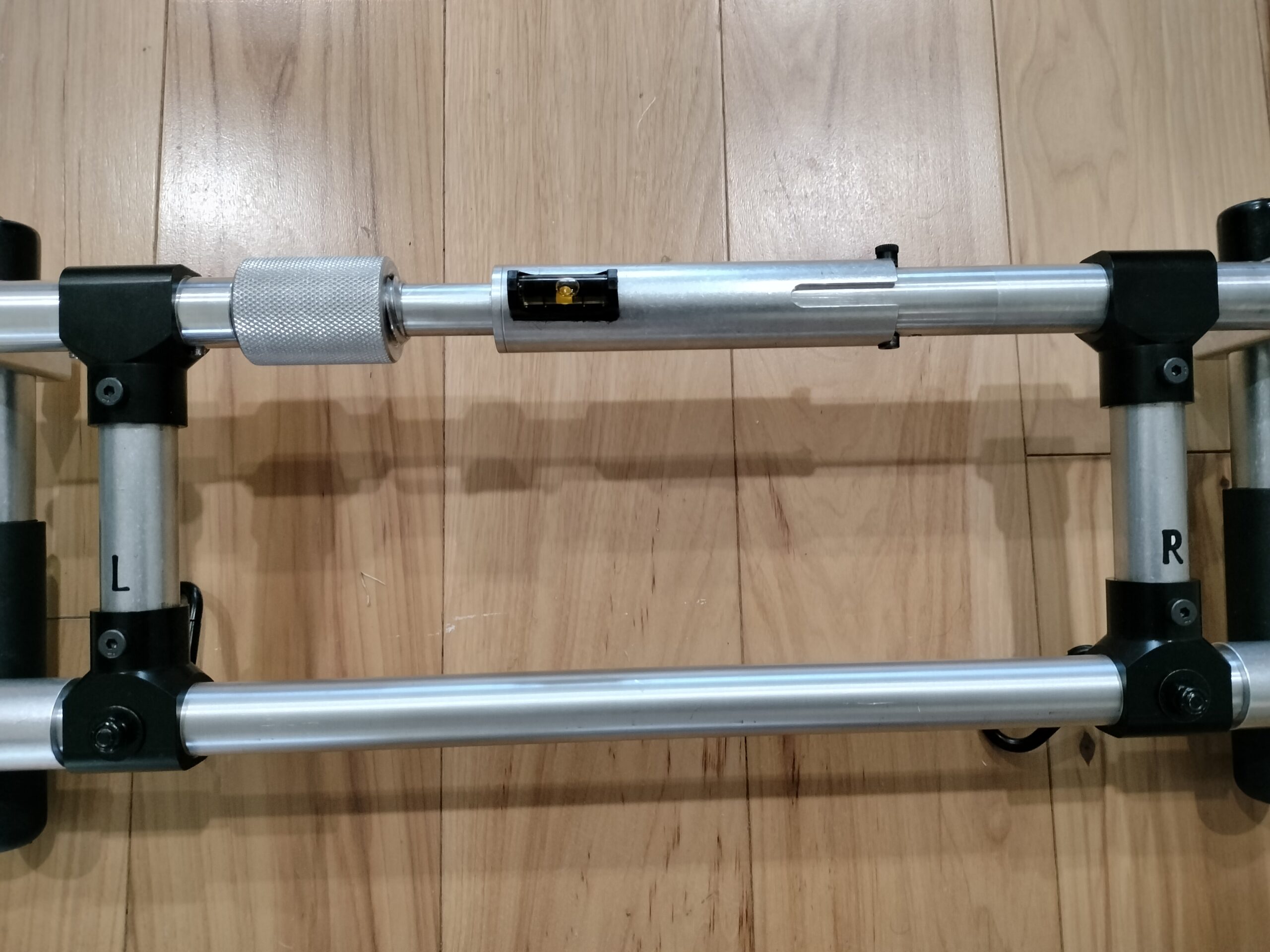
Mini level – 1
Rubber bumpers – 4
Carabiners – 4
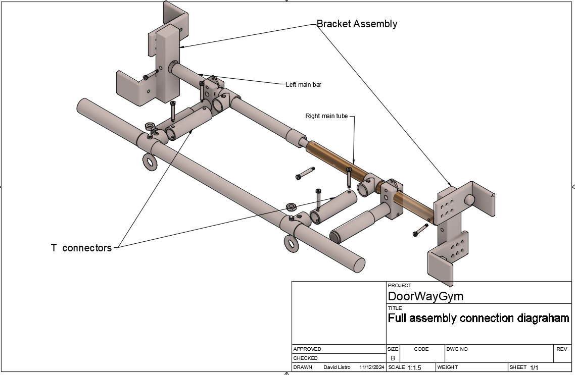
Full Assembly
Full assembly2
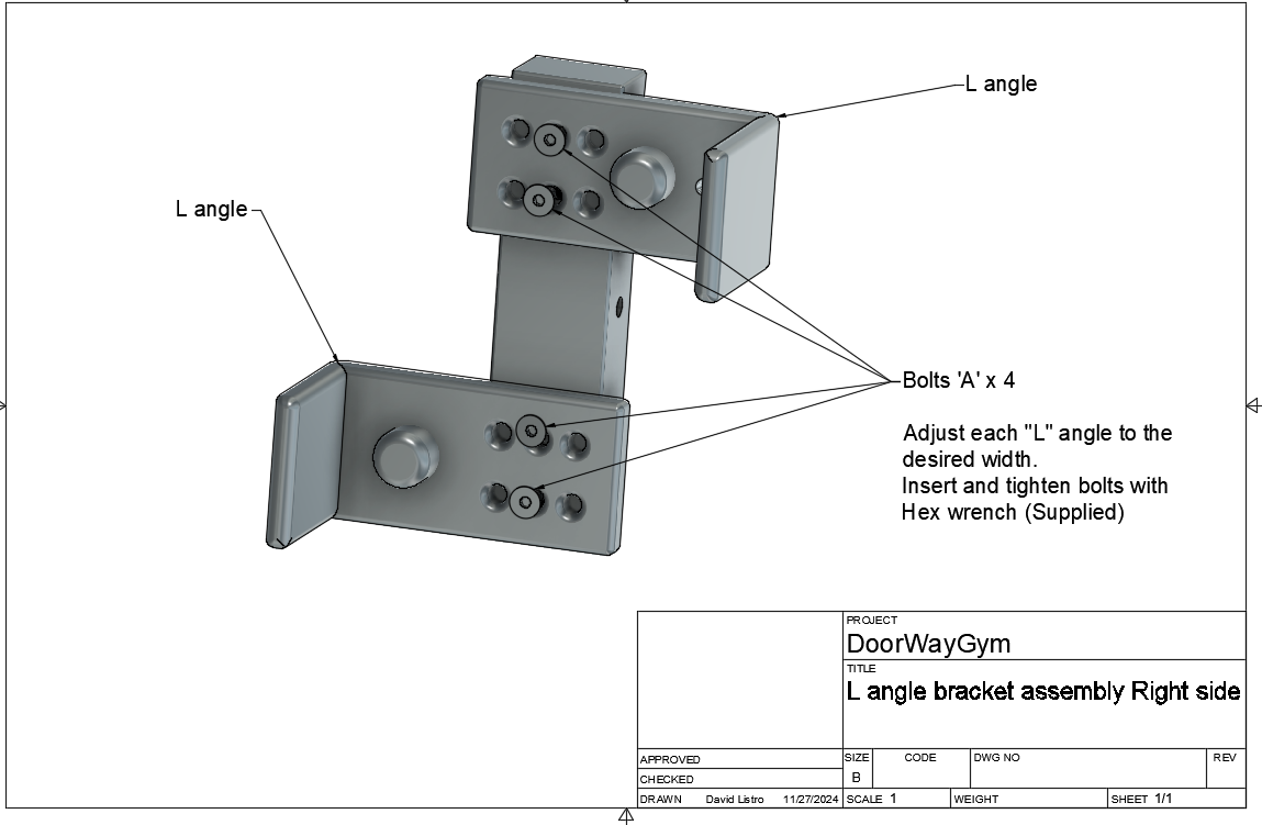
Step 1
L angle bracket assembly right side
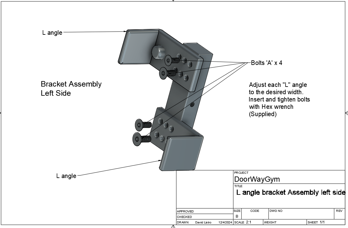
Step 2
L angle bracket assembly left side
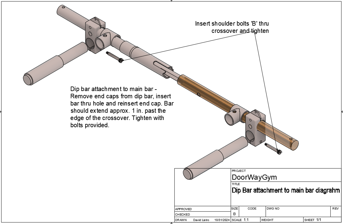
Step 3
Dip bar attachment to main bar - Remove end caps from dip bar, insert bar thru hole and reinsert end cap. Bar should extend approx. 1 in. past the edge of the crossover. Tighten with bolts provided.
Step 4
Swing bar to main bar assembly
Step 5
Left main bar to angle assembly2
Step 6
Right main bar to angle assembly2
Set T connector L-R tubes as shown
Scan code for updated assembly instructions